editorial
editorialentrevista
interviewartigo convidado
invited paperartigos submetidos
submitted paperstapete
carpetartigos nomads
nomads papers-
projeto
project -
resenha
review -
eventos
events

issn 2175-974x | sem02-11


Knitectonics
Sanhita Chaturvedi é Arquiteta e Mestre em Novos Métodos para Fabricação Digital, Design e Urbanismo. Atualmente trabalha na Foster + Partners Architecture.
Esteban Colmenares é Arquiteto e Mestre em Novos Métodos para Fabricação Digital, Design e Urbanismo. Professor Visitante na Universidade de Central Lancashire, John McAslan + Partners.
Thiago S. Mundim é Arquiteto e Mestre em Novos Métodos para Fabricação Digital, Design e Urbanismo. Professor Visitante no Instituto para Arquitetura Avançada da Catalunha (IaaC) e atual diretor do YNOYarchitecture.
Como citar esse texto: CHATURVEDI, S.; COLMENARES, E.; MUNDIM, T. S. Knitectonics. Traduzido do inglês por João Paulo Soares. V!RUS, São Carlos, n. 6, dezembro 2011. Disponível em: <http://www.nomads.usp.br/virus/virus06/?sec=4&item=2&lang=pt>. Acesso em: 05 Jul. 2025.
Resumo
“...técnicas que operam a nível material, se precisamos de ideias, seguirão a partir de técnicas e técnicas seguirão a partir de matéria...” - Gottfried Semper (1851, tradução nossa)
É possível uma simples máquina de artesanato doméstico facilitar um sistema proto-tectónico?
O projeto Knitectonics visa explorar sistemas de fabricação digital que facilitem soluções arquitetônicas integradas, otimizadas e adaptativas (Malé-Alemany, 2009). Ele é inspirado pela beleza de sistemas naturais e sua inerente eficiência e desempenho. A pesquisa explorou a fabricação em campo de cascas estruturais únicas, integrando pele e estrutura, juntamente com serviços e infraestrutura, utilizando uma simples técnica caseira. Assim, incorpora um micro sistema de texturas e um macro sistema de estruturas, auto-organizado. Este artigo descreve como aspectos numéricos de técnicas têxteis foram usados, primeiramente para digitalmente imitar o processo de montagem e depois explorar e desenvolver um novo sistema de fabricação, com base em pesquisa de materiais e experimentação prática.
Palavras-chave: Fabricação digital, arquitetura emergente, arquitetura evolutiva, arquitetura textil, malha, pesquisa em design.
1. Introdução
Sempre existiu uma harmonia natural entre máquinas e matemática, e essa sincronização direcionou os cientistas à computação atual. O tear Jacquard, com seus cartões de madeira perfurados, foi o primeiro dispositivo mecânico que funcionou com um padrão binário. Ele trouxe a ideia de programação e ainda inspirou Charles Babbage a desenvolver o engenho analítico (Chisom, 2011). Desde a revolução industrial, as técnicas para manipulação de fibras em produtos têxteis não seguem procedimentos artesanais caseiros, nem os materiais estão sujeitos à quebra. Juntos, materiais e técnicas tem sido revolucionários, tanto é que hoje são usados para vários propósitos de alta-performance, como construção de aeronaves. Todas essas técnicas trabalham com o arranjo de materiais, para diferenciar padrões de superfícies e formas geométricas. Esta pratica esta em forte congruência com a arquitetura, mas na ausência de um projeto e ferramenta de visualização, o seu potencial ainda não foi totalmente aproveitado.
A relevância fortemente enraizada da produção têxtil em arquitetura é evidente nas obras teóricas do arquiteto alemão, do século XIX, Gottfried Semper, que inferiu que a produção têxtil foi a primeira arte técnica. Lars Spuybroek vislumbrou a possibilidade de transformar elementos flexíveis em rígidos através da colaboração entre várias técnicas de construção têxtil. Essas intuições teóricas em conjunto com a capacidade dos “tecno-têxteis” disponíveis poderiam ser unidas com processos mecânicos simples usados na indústria têxtil. Para esse fim, inúmeras técnicas de Intercalamento (como o posicionamento das fibras, tecelagem e costura 3D), Entrelaçamento (como tranças e nós) e Costura (tricô) foram estudadas e experimentadas.
O objetivo primário desse projeto foi alcançar geometrias complexas com inerente ‘economia de meios’, utilizando o material de maneira otimizada. Monocoques, onde a pele é também estrutura, visivelmente ilustram isso e o objetivo era estender essa economia para outros parâmetros de material, máquinas, infraestrutura, energia e tempo criando ‘formas auto estruturadas’. A técnica de confecção de malhas tricotadas usa o potencial de mono-materiais contínuos como a fibra e apresenta a possibilidade de materializar estruturas unificadas sem a necessidade de fôrmas, contra outras técnicas têxteis que podem requerer configurações de máquina complexas e a utilização de moldes. Assim, a reinterpretação de um método existente e a articulação com uma sofisticada programação de um sistema mecânico para a exploração de novos processos de projeto arquitetônico, será demonstrada aqui com técnicas de confecção de malhas tricotadas.
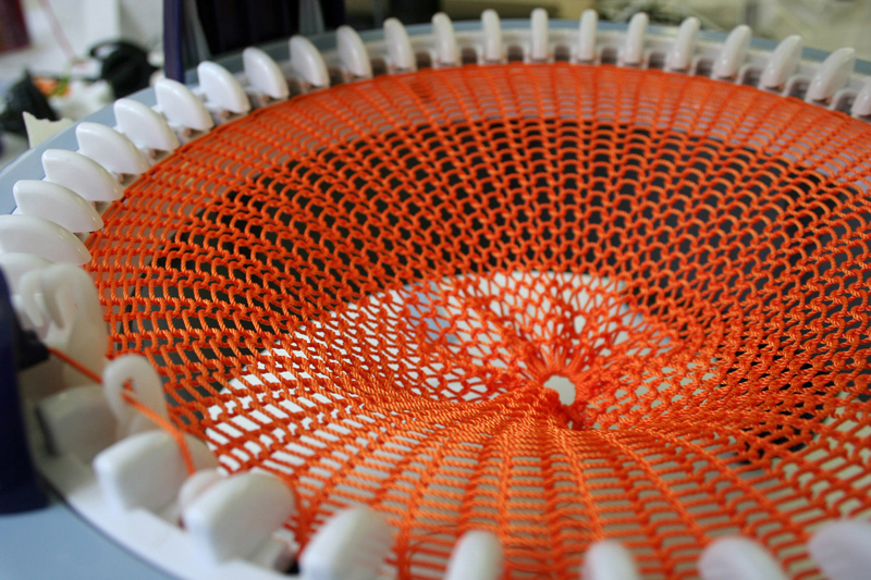
Figura 1. Máquina Caseira de Tricô Circular.
2. Evolução da Máquina
O processo desenvolvido na elaboração do projeto foi um diálogo paralelo entre experimentos analógicos, realizados utilizando uma máquina de tricô circular caseira (Figura 1) e simulações digitais, realizados utilizando linguagem Java na plataforma ‘Processing’. Após a compreensão da máquina, do método e da metáfora do tricô, o desafio foi explorar as possibilidades tectônicas apresentadas pela técnica, resolver o problema de escala como um protótipo arquitetônico e adaptar o sistema para implantação em um terreno real. O primeiro passo para uma solução foi conectar duas ou mais máquinas com uma ponte, inspirado pela ‘máquina de tricô para a produção de meias’ de Benito Manini[1]. Assim, embora o design do protótipo conceitual da máquina tenha começado com uma máquina caseira circular, evoluiu através de configurações retilíneas, cruciformes e hexagonais, para, posteriormente, voltar a uma configuração circular, ligada por pontes em uma grelha hexagonal (Figura 2).
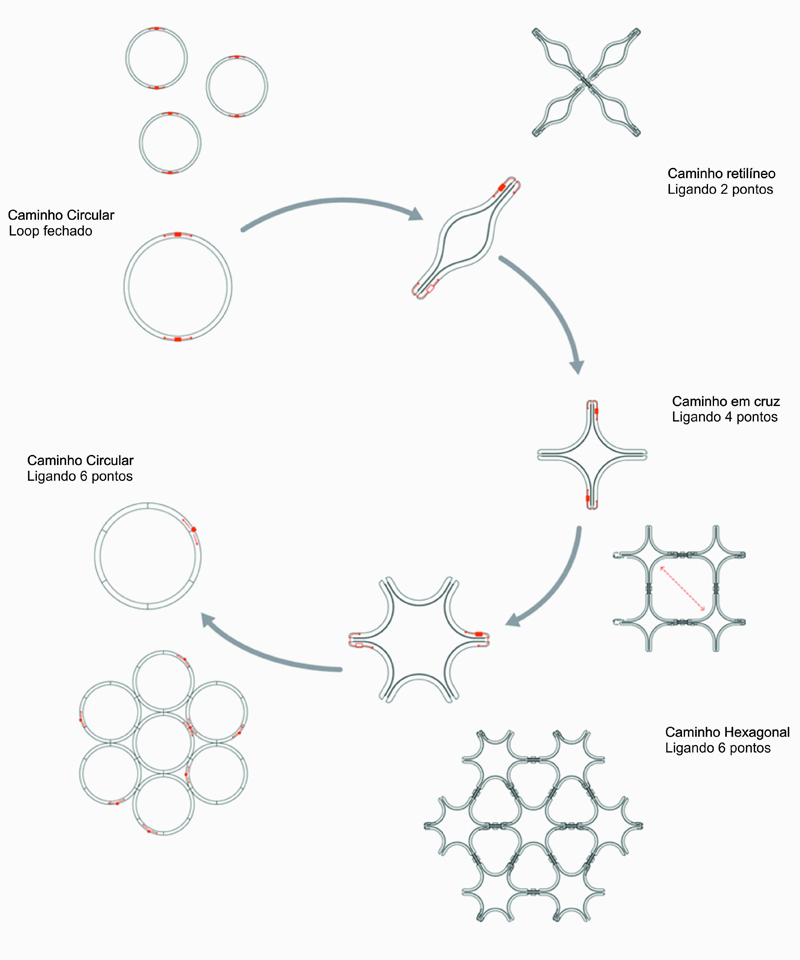
Figura 2. Evolução da Máquina.
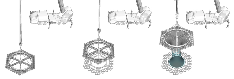
Figura 3.Malha – Ligação – Anel de Solidificação.
Para ser viável como um processo de fabricação, a configuração digital da máquina de tricô circular com pontes exigiria elementos adicionais a seu funcionamento. Para criar estruturas sem fôrmas com este sistema, o ‘anel de tricô’ proposto moveria para cima costurando a malha que seria tensionada utilizando uma replica do ‘anel de fixação’, dentro da configuração da máquina, preso ao chão. Outro aspecto crítico era alcançar rigidez estrutural, a solução sugerida foi a utilização de fibras impregnadas com resina, que se solidificariam através da aplicação de raios UV vindos do ‘anel de solidificação’ (Figura 3). Para investigar e simular aspectos sistêmicos e a complexidade topológica com a máquina de solidificação de malhas, foi imperativa a construção de um protótipo digital. A ideia foi criar um sistema de simulação que poderia imitar digitalmente todas as partes da máquina e suas ações, para criar a estrutura em malha. Assim, as ferramentas em conjunto representam uma nova linguagem de montagem que será explicada aqui como três fases.
A primeira fase de desenvolvimento de uma ‘ferramenta de decodificação’ envolveu o entendimento e a desconstrução das ações para costura da máquina e das propriedades materiais das fibras utilizadas, para posteriormente traduzi-las em uma malha, com seus comportamentos específicos. Essa ferramenta facilitou a apreciação e especulação de padronizações, topologias e comportamentos, além da capacidade da máquina analógica.
A segunda fase da simulação ajudou a conceituar o ‘aparelho de design’, com a interface como um diagrama de fabricação. O aparelho de design é baseado na compreensão sistêmica de uma máquina simples, onde a fibra construída articula perfeitamente superfície e camadas, sendo que e trajetória de uma única linha gera geometrias de uma, duas e três dimensões(Baumann, 2010). A interface permite a seleção do tamanho e configuração das máquinas, tipo e propriedades das fibras, dinâmica e equilíbrio do sistema e o curso da ação dos ‘agentes’ de alimentação da fibra. Os algoritmos implementados facilitaram a opção por sequências de cabeçotes pré-programados ou ajustados em tempo real e a visualização dos resultados. O sistema mecânico digital foi então aplicado em um cenário específico, para testar e demonstrar a capacidade tectônica do método desenvolvido.
A terceira fase propôs uma ‘ferramenta generativa’ que poderia ser desenvolvida no futuro para avaliar, selecionar e otimizar. Os sistemas digitais oferecem várias maneiras de configurar, sequenciar e controlar a máquina, de tal forma que o sistema não forneça um único resultado preciso, mas várias soluções adequadas. As constantes do sistema, ou seja, os ‘cromossomos’, são variados para alcançar uma população aleatória. Estas iterações são avaliadas em função dos parâmetros prescritos e, em seguida, criadas ao longo de dez gerações para obter soluções arquitetônicas adequadas.
3. Ferramenta de Decodificação
Na fase inicial de simulação digital, o sistema de decodificação pôde simular diferentes fios com propriedades variadas, aberturas, diferentes padrões e solidificações, sob o efeito da gravidade e do tempo (Figura 4). A simulação foi focada principalmente em imitar digitalmente o comportamento e padronizações do tecido, com a compreensão da máquina analógica.
As partes da máquina que executam diferentes funções que foram divididas em diferentes tarefas dentro do sistema de simulação, tais como as pistas, o alimentador de fios e as ligações da ponte. O script de simulação foi escrito em ‘Processing’ (Frey; Reas, 2010) e para simulações físicas foi utilizada uma biblioteca adicional ‘Toxiclibs ’(Schimidt, 2010).
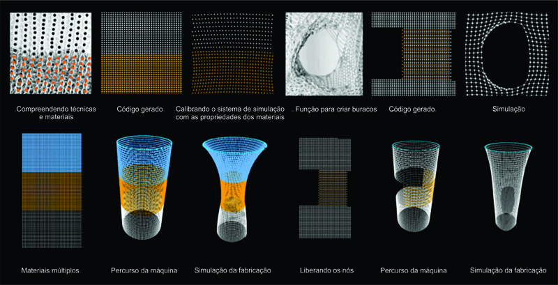
Figura 4.Processo de Decodificação Analógico e Digital.
3.1. Partes do Sistema
- Agulhas: é o menor componente de desempenho do sistema mecânico. Elas trançam os fios para criar a malha tricotada, enquanto seguram o primeiro nó para trançar o próximo conjunto de nós.
- Cama de Agulhas: é um seguimento da pista que serve como base para as agulhas. Cada cama tem certo número de agulhas e uma "ponte" no início da mesma.
- A Ponte: é o ponto em que duas camas de uma mesma pista são ligadas. Estes também se tornaram os pontos de conexão para a ligação com outras pistas.
- A Pista: é composta por seis camas de agulhas, e carrega a informação requerida para criar uma máquina de tamanho específico, isto é; raio, número total de agulhas e etc. Estes parâmetros determinam as especificidades das camas e das agulhas. Cada pista possui seis camas e, portanto, seis pontes, a cada 60 graus, que se conectam a outras pistas (Figura 5).
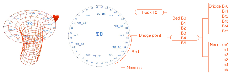
Figura 5.Anatomia da Máquina.
3.2. Ação de Tricô
O processo de confecção de malhas em uma máquina física envolve cada agulha de tricô para criar um ciclo. Este ciclo é mantido até os fios chegarem ao entre-ciclo para criar um novo ciclo, sendo assim em seguida, os nós soltos, criando-se o tecido. Por isso, cada nó esta singularmente ativo quando junto à agulha, e uma vez solto da agulha como parte do tecido, ele passa a fazer parte de uma ação coletiva. Na simulação cada nó na agulha é representado por uma ‘partícula’. Estas ‘partículas’ quando soltas das agulhas, e configurando o tecido, podem ser descritas como um ‘número de partículas’ conectados com ‘molas’, consideradas como o equivalente digital do fio.
[1] Benito Manini, ‘Knitting Machine for Producing Tights’, Patente dos Estados Unidos, número 5.226.297. 13 Jul. 1993.
3.3. Tecido Tricotado
Cada fio utilizado no tricô possui propriedades específicas e se torna indispensável incorporar esses dados dentro da simulação para obter uma imagem real do comportamento dos materiais. Com a queda do tecido tricotado através da gravidade, os comportamentos dos fios governam o comportamento do tecido. Assim, no script de simulação, cada fio possui as seguintes características.
- Física: Os nós do tecido são representados por ‘partículas’ conectadas com ‘molas’ da biblioteca com os algoritmos de física. Estas ‘partículas’ são submetidas à força da gravidade e a outras energias ao seu redor uma vez que os nós são relacionados e colidem entre si.
- Força do Fio: Os fios são diferenciados pela força de cada ‘mola’ de cada fio. A força elástica é definida por um intervalo de estiramento máximo e compressão máxima e uma posição de repouso ideal, de tal forma que as molas, sob a ação de todas as forças, tendem a voltar à posição de repouso.
- Peso dos Fios: Sendo a força aplicada a um objeto o produto da sua massa pela aceleração gravitacional, para calcular a força do fio, a gravidade é declarada como uma variável global e o peso de cada fio é definido em suas propriedades (Figura 6).
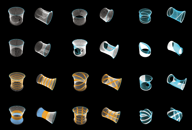
Figura 6.Possibilidade de Versões do Material.
3.4. Dinâmica da Máquina
No tricô convencional, a máquina está parada e o tecido é pressionado em rolos e puxado para baixo. No modelo conceitual, a máquina se move para cima enquanto tricota, e a gravidade e o solo são utilizados para prender e tensionar o tecido. As funções a seguir são utilizadas para simular a dinâmica do sistema em tempo real.
- Fixação do Tecido: Esta função permite a fixação do tecido ao solo ou a qualquer outro plano horizontal, sendo a distância após a fixação passível de ser ajustada através da interface. Aqui a primeira linha de ‘partículas’ nas agulhas da máquina, estão conectadas aos correspondentes pontos no plano de fixação.
- Movimento da Máquina: Esta operação ativa a movimentação vertical da máquina. A velocidade do movimento pode ser ajustada conforme a tensão necessária: um tecido de malha apertada exigiria uma alta velocidade e um tecido de malha solta requereria uma velocidade lenta.
- Tensão: Esta é uma necessidade absoluta para o tricô analógico e é obtida utilizando pesos. No sistema digital, a tensão derivada é uma combinação da velocidade de movimentação da máquina e o atrito causado pelo plano de fixação (Figura 7).
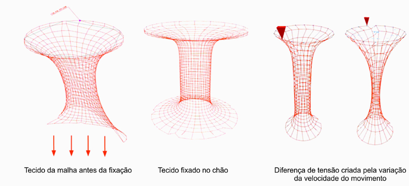
Figura 7.Dinâmicas da Máquina.
3.5. Materialidade
As implicações de se tricotar múltiplos fios simultaneamente foram estudadas em experimentos analógicos. Estando dentro do campo de compostos de fibras, matrizes de materiais para solidificação dos fios foram utilizadas e, depois, a possibilidade de uma combinação entre fibra e matriz em um único material, por exemplo o fio impregnado. Estes foram integrados à simulação.
- Múltiplos Fios: Cada fio único possui propriedades específicas, assim para combinar múltiplos materiais, a simulação cria um novo material com uma identidade distinta combinando as propriedades dos diferentes fios utilizados.
- Solidificação: Esta função imita a máquina e instiga o processo de solidificação do fio após ele ser tricotado. Para solidificar os nós, a simulação bloqueia a elasticidade das ‘partículas’ envolvidas.
- Fio Impregnado: O tecido tricotado pode ser flexível e rígido, portanto, o sistema digital também necessitava da flexibilidade para seletivamente solidificar um fio específico e não todos os fios. Dessa maneira a simulação leva em conta fios impregnados estruturais. (Figura 8).
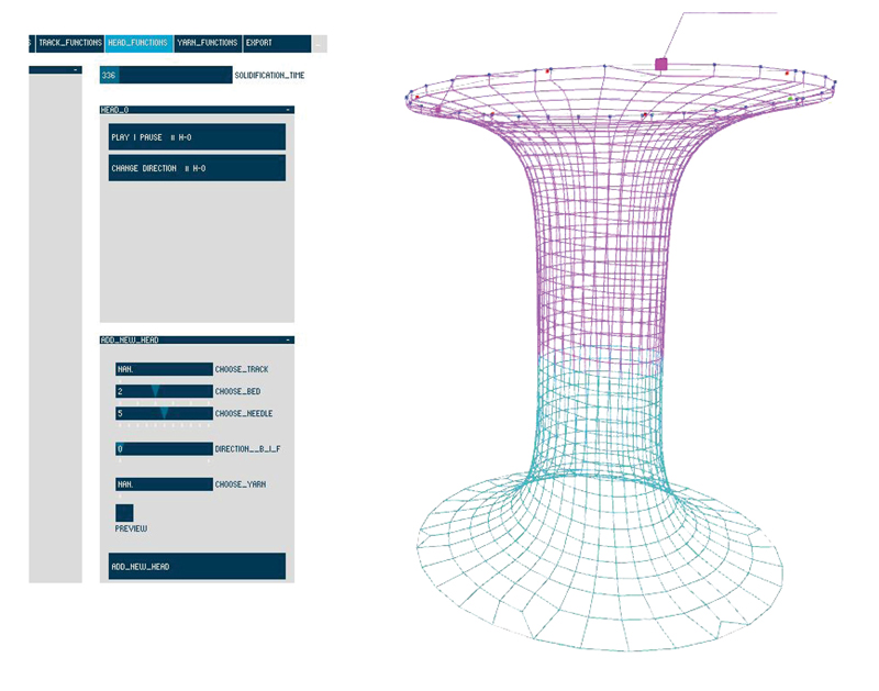
Figura 8.Materialidades – Tricotado (Magenta) e Solidificado (Azul).
4. Ferramenta de Design
Após decodificar as ações para o tricô e todas as partes da máquina proposta, a ferramenta foi utilizada para a criação de projetos. Os múltiplos cabeçotes foram programados para tricotar ao longo das pistas e a responder às pontes. (Figura 9)
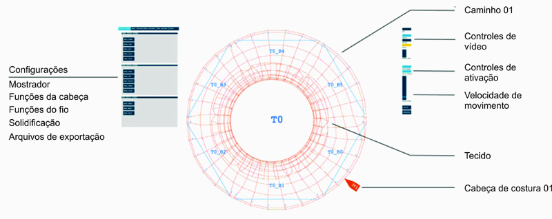
Figura 9.Desenho da Interface do Aparelho de Design.
O cabeçote carrega o fio e solta as partículas conectadas com molas ao longo da pista. Após a introdução da função da ponte, o cabeçote pode mover-se de uma pista para a outra. A ativação da ponte e sua rotina podem ser predefinidas no script ou modificadas em tempo real através da interface. Rotinas de ativação-desativação da ponte e cruzamento entre pontes, facilitam a criação de conexões, bifurcações e topologias.
4.1. Sequências de Cabeçotes
Melhorias no design da máquina levaram à dedução que a ponte não era necessária como um elemento físico, mas sim como uma ação dos cabeçotes. Em qualquer ponto de conexão de duas pistas na grelha hexagonal do arranjo circular, o cabeçote pode realizar qualquer uma das quatro ações prescritas. Essas ações são referenciadas como ‘sequências’.
- Sequência 0: A ‘sequência 0’ é o comando para o cabeçote ignorar um ponto de conexão.
- Sequência 1: A ‘sequência 1’ para o cabeçote retornar.
- Sequência 2: A ‘sequência 2’ para o cabeçote criar uma ponte.
- Sequência 3: A ‘sequência 3’ para o cabeçote cruzar ponte (Figura 10).
É importante notar que este ‘ponto de conexão’ une duas agulhas em uma pista à duas agulhas correspondentes em outra pista. Assim, na sequência 2, o cabeçote cria uma ponte entre duas agulhas localizadas em paralelo, enquanto que na sequência 3, o cabeçote cria uma ponte através de duas agulhas localizadas em diagonal e costura tubos em conjunto. A cada cabeçote pode, portanto, ser prescrita uma rotina de 'n' números em sequências e essa rotina pode repetir indefinidamente.
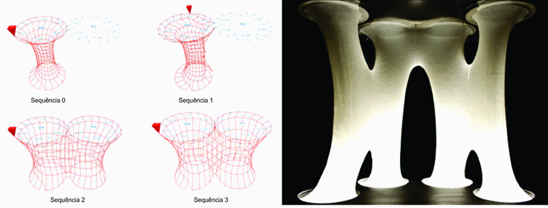
Figura 10.Sequência digital e uma Instância Analógica da Combinação de Sequências.
4.2. Ponto de Início do Cabeçote
Na configuração de uma grelha hexagonal fechada com três ou mais pistas, há um perímetro externo e um perímetro interno, fechado dentro das pistas. O ponto de início do cabeçote no exterior em relação ao perímetro interno pode produzir resultados diferentes. O ponto inicial do cabeçote pode ser direcionado, especificando-se uma pista, a cama de agulhas, a localização numérica da agulha, e a orientação do movimento como sentido horário ou anti-horário. Como o trajeto do cabeçote é prescrito pela rotina de sequências, o resultado de malha é específico para o ponto de início na configuração das pistas.
4.3. A solta dos Nós
A densidade da malha pode ser alterada e furos podem ser criados ao se soltar os nós das agulhas. A ideia da máquina digital é experimentar com topologias e aberturas em uma escala apreciável, assim o foco estava em soltar os nós não apenas de agulhas individuais, mas sem para grupos de agulhas. O sistema de simulação ofereceu a possibilidade de soltar uma pista inteira ou camas de agulhas especificas de uma pista, ou ainda, apenas a ponte, de acordo com os pré-requisitios de design na aba ‘funções das pistas’ na interface de projeto. (Figura 11)
4.4. Número e Trajeto do Cabeçote
Como mencionado anteriormente, existe um perímetro externo e interno fechado dentro das pistas. Esses perímetros – a pista propriamente dita (perímetro maior) e os interstícios criados (perímetro menor) – podem ambos ser empregados como trajetos para os cabeçotes. Curiosamente a velocidade dos movimentos da máquina se torna crítica a partir do momento em que o tempo requerido para cada perímetro se torna diferente, o que pode causar ou que o tecido interno se torne muito solto ou o tecido externo muito tensionado. Isso pode ser contornado com a inserção de mais pontas no perímetro maior. Estes interstícios proporcionaram a possibilidade de variar os volumes fechados das malhas e criar elementos estruturais, subdivisões e veios. (Figura 11)
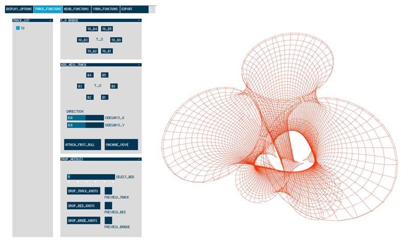
Figura 11.Interface de solta dos Nós / Modelo com Variação de Perímetro.
4.5. Controle de Fixação
Juntamente com todas as funções apresentadas acima dentro do sistema digital, a opção por fixar ou não fixar em qualquer momento específico e a possibilidade de fixação no solo ou em qualquer outra superfície plana, abre um novo campo de possibilidade para topologias e morfologia (Figura 12).
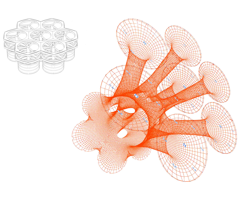
Figura 12.Configuração com Sete Pistas e a Possibilidade Gerada.
5. Aplicação na Arquitetura
A interface de projeto foi desenvolvida a partir do entendimento de técnicas analógicas, sistemas mecânicos e comportamento dos materiais. A ferramenta de design contém todo o conhecimento obtido através da ferramenta de decodificação e da oportunidade de vislumbrar o tricô como um princípio de construção. A coreografia dos cabeçotes determina a maneira como o material construído e define um novo vocabulário para a arquitetura.
As configurações permitem obter superfícies topológicas complexas uma vez que a máquina possui uma relação um-a-um com o material resultante e a as coordenadas naturais locais criam uma estrutura global-local. Além disso, para abordar questões de nível macro e micro com o sistema, foi introduzida a ideia de uma máquina de tamanhos variados através de uma grelha hexagonal, assim agregando a capacidade de integrar múltiplas escalas, resoluções e funções. Os aspectos tectônicos são direcionados a dois níveis do sistema, primeiramente a um nível espacial ou programático, fornecendo espaço, estrutura e furos, e em segundo lugar um nível performático, proporcionando micro infraestrutura, serviços incorporados e casca performativa (Figuras 13a, 13b e 13c).
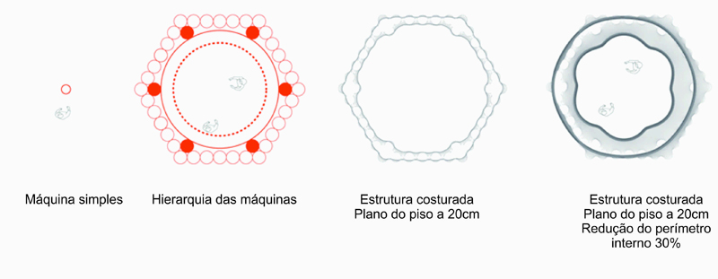
Figura 13a.Dimensões e Hierarquia da Máquina.
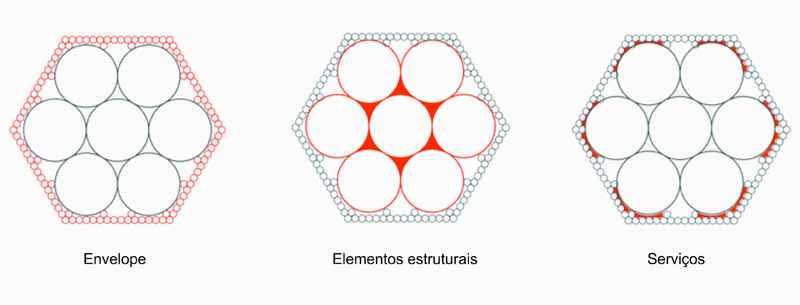
Figura 13b.Resolução e Relacionamento entre Elementos Tectônicos.
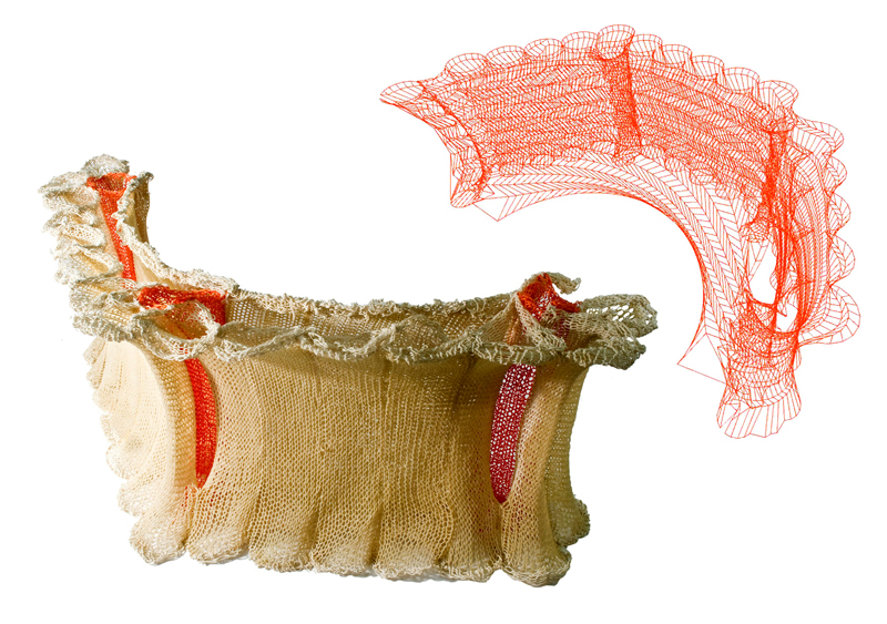
Figura 13c.Relacionamento Analógico-Digital entre Elementos Tectônicos.
O sistema foi analisado para colocar em prática de maneira apropriada o método reinterpretado. Sendo multiescalar, modular e colaborativo, possui potencial para atender a várias escalas, programas e situações, podendo se adaptar às restrições de locais através da implantação flexível e de abordagens de uso de material disponíveis. O sistema possui uma natureza de aplicação como protótipo no campo de instalações rápidas, de mínimo impacto através da integração de um sistema único. As múltiplas camadas interconectadas propiciam a oportunidade de implementar micro infraestruturas e serviços dentro de uma estrutura unificada, tornando-o adequado à infraestrutura de nível macro.
Para testar o sistema foi escolhido como cenário de aplicação o desenvolvimento de uma nova infraestrutura para uma nova tecnologia de transporte – o sistema Personal Rapid Transit (PRT) na cidade de Bath. A estética, leveza e transparência dos tecidos, adequadamente o situam em uma cultura profundamente enraizada de produção têxtil em cidades históricas inglesas. O Sistema PRT demonstra ressonância com as topologias de malhas criadas pelo sistema mecânico proposto, através dos conceitos de continuidade/bifurcação, redes/nós (Figuras 14a e 14b).
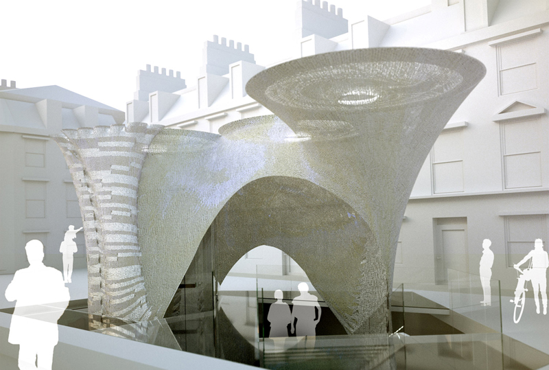
Figura 14a.Aplicação na Arquitetura / Estação PRT Canopy em Bath.
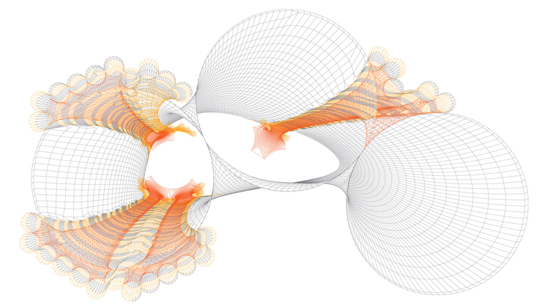
Figura 14b.Plano da Cobertura da Estação PRT Canopy, Demonstração da Ferramenta de Projeto.
Diferentes localidades por onde a infraestrutura do PRT se estende dentro de outras infraestruturas da cidade foram selecionadas para explorar a natureza do protótipo do sistema com base no programa, escala, contexto, configurações da máquina e material. (Figura 15). Embora todas as estações utilizassem o mesmo sistema, o design e a abordagem de implantação de cada uma variou, assim testando e demonstrando a viabilidade do sistema e também definindo seus limites e alcances.
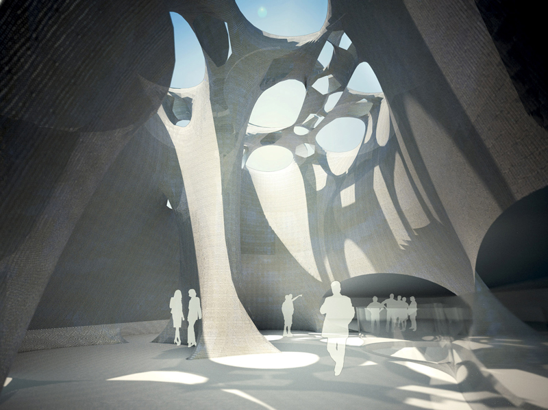
Figura 15.Aplicação / Museu de Arte e Estação PRT Subterrânea em Bath.
6. Ferramenta Generativa
A ferramenta de projeto aqui proposta facilita a realização da maioria das tarefas que trabalham com materiais convencionais e máquinas envolvidas na produção de arquitetura. O sistema mecânico digital proporciona várias opções de configurações em termos de número de pistas, seus arranjos, conexões de pontes, números de cabeçotes de costura, pontos de início e tipos de fios utilizados. Junto com o controle de fixação, movimentação e solidificação, e mais importante, as sequências prescritas para os cabeçotes, as permutações e combinações possíveis são infinitas.
O sistema fornece múltiplas soluções com equivalente adequação, assim tornar-se-ia extremamente complexo chegar aos mesmos resultados de maneira linear (Alfaris e Marello, 2008). Com o objetivo de criar soluções arquitetônicas apropriadas, somente um sistema generativo poderia se capaz de avaliar, selecionar e otimizar requisitos para o modelo arquitetônico proposto.
A terceira ferramenta –os algoritmos generativos – foi uma modesta tentativa para gerar uma gama de valiosas soluções arquitetônicas através do sistema mecânico proposto com base na concepção estrutural e na análise do espaço. Com precisão e sofisticação melhoradas, o procedimento poderia ser uma ferramenta de otimização de objetivos e no futuro poderia ser ampliado para outros parâmetros físicos e de performances como aberturas, alturas, resolução de superfícies, camadas e etc..
Para entender sistemas generativos, tomamos como referência o artigo de Anad Alfaris e Ricardo Merello ‘The Generative Multi Performance Design System’ apresentado no ACADIA 2008. O artigo propõe um quadro de soluções generativas com o desenho de espaços definidos através da linguagem de criação de sistemas, com a integração de vários critérios de desempenho. O sistema é composto de quatro fases, nomeadas: síntese, análise, avaliação e otimização. Através deste ciclo, armazenam-se módulos de parâmetros, constantes e restrições. Para testar a viabilidade de um sistema generativo através da comparação de diferentes iterações buscando a solução ótima, esses ciclos foram aplicados ao sistema mecânico digital aqui apresentado.
- Síntese: Parâmetros básicos da arquitetura em relação a estrutura e espaço, em que se estabelece as intenções de projeto.
- Análise: Desde que a força da gravidade e a movimentação vertical da máquina de tricô controlam a fabricação do tecido, a estrutura é caracterizada pela tensão existente nos nós. O espaço é incorporado na dimensão do invólucro criado.
- Avaliação: para entender o esforço em diferentes regiões e as alterações nas sessões de cruzamento nos dois eixos do tecido tricotado, modelos físicos foram estudados.
Computacionalmente, para avaliação estrutural, o sistema mede as forças de tensão (a força elástica em comparação a força de retorno a posição de repouso) agindo em cada nó e sua caracterização quando: mais alongado, delongado, e idealmente alongado, com base na calibragem de modelos físicos. Na simulação proposta, o alongamento ideal é demonstrado pela cor verde, o mínimo alongamento é representado pela cor azul e o alongamento moderado e representado em amarelo. A cor vermelha representa o alongamento limite, além do qual a elasticidade está no ponto de ruptura e, portanto, inadequado, mostrado em preto.
A partir de modelos físicos concluiu-se que um tecido de malha normalmente se estende até um terço do comprimento original. Considerando o comportamento de auto-organização dos nós, a implicação do aumento do comprimento é visível na seção transversal reduzida do tubo. Assim, para avaliação espacial, a menor dimensão para espaços ainda habitáveis é estabelecida baseada no tamanho da máquina e a percentual diminuição da seção após o alongamento. As opções foram avaliadas em relação a essa dimensão mínima, descartando opções inviáveis (Figura 16).
- Otimização: Tipicamente, a solução ideal poderia ser escolhida, comparando-a contra a "melhor solução pré-definida". Mas o sistema proposto não possui soluções ideias pré-definidas, assim cria-se o desafio de apresentar a solução ideal através de uma serie de possibilidades.
“A evolução começa a partir de um conjunto de soluções de design geradas aleatoriamente para guiar a evolução. Não se propõe produzir uma solução global ideal, mas sim dirigir o processo evolutivo para produzir um conjunto de boas soluções” (Alfaris; Merello, 2008). Esse algoritmo de evolução pode ser decomposto em cinco estágios: função de aptidão, mecanismo de seleção, acoplamento, acasalamento e introdução de mutação (Rutten, 2010). Aplicando esses princípios para desenvolver uma ferramenta de otimização, as constantes ou os cromossomos foram definidos em respeito às configurações das pistas e a localização dos cabeçotes. O primeiro conjunto de cem iterações foi gerado por uma combinação aleatória de sequências 0, 1, 2 e 3 (0=continue, 1=volte, 2=vá até a ponte e 3=cruze a ponte) que são comparáveis aos genes ou ao DNA na evolução biológica.
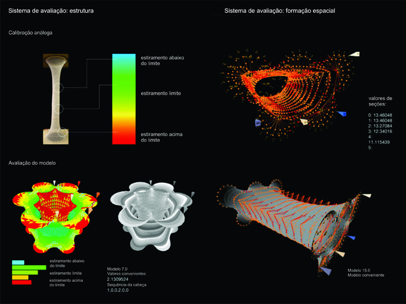
Figura 16.Avaliação dos Parâmetros da Estrutura e dos Espaços.
Iterações foram avaliadas em função dos parâmetros da estrutura e do espaço e atribuídas um valor de aptidão. Para avaliação estrutural, a aptidão é determinada pelo número de nós idealmente esticados, como um valor com peso positivo e o número de nós com estiramento máximo e nós com estiramento mínimo, como um valor com peso negativo. Estas foram as medidas para obter o valor de aptidão. Similarmente, para avaliação espacial, a distância dos ‘espaçamento das células’ em cada segmento da superfície desde o eixo central é medido em relação à distância ideal prescrita e, em seguida, em média, em todo o envelope.
Das cem iterações, são selecionadas como as melhores, dez iterações com os maiores valores de aptidão estrutural e espacial. Essas dez iterações são acopladas com mais dez iterações geradas da mesma maneira para gerar a prole da segunda geração. Esse processo é repetido por mais dez gerações. Curiosamente, as dez iterações resultantes tendem a ser similares a partir da sétima geração (Figura 17).
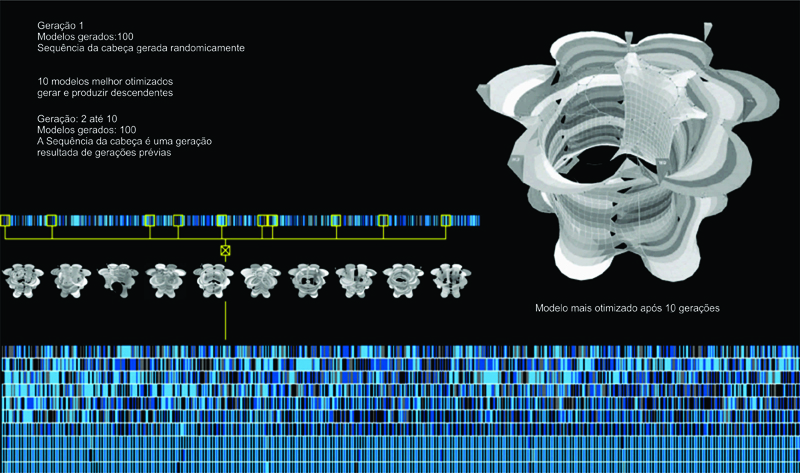
Figura 17.Algoritmo Genético Desenvolvendo Interações a partir de Dez Gerações.
7. Conclusão
As fibras trabalhadas criam e articulam superfícies e camadas e a partir da trajetória de uma única linha surge uma/duas/três geometrias dimensionais – Auto similar e repetitiva, de vínculos entrelaçados e sequência perfeita – De regras locais que definem uma linguagem de montagem que produz resultados globais dinâmicos – Com um material antes sem valor que se transforma. Essa é a riqueza de uma técnica artesanal.
A técnica pré-concebidos através de instruções pré-programadas no tear jacquard, deu lugar a computação. Com uma máquina de fabricação local, inspirada por uma técnica caseira, que recebe o feedback da materialidade e responde a ela, as três ferramentas do sistema proposto usam a computação para o design, visualização, instrução e fabricação em tempo real.
‘Knitectonics’ é nosso humilde esforço para reinterpretar um sistema mecânico e uma técnica existente para articular novos processos de criação em arquitetura. Nossa tentativa, de uma maneira inicial, foi de explorar diversos índices de sistemas mecânicos, materialidades, implantação, topologias, estratificações, escalas, parâmetros, algoritmos e etc.
Contemplando um futuro para o projeto, existem várias preocupações em potencial para nos focarmos. Como mencionado anteriormente, o algoritmo generativo é uma possibilidade para uma ferramenta de otimização dos objetivos, mas no isolamento de uma série de preocupações subjetivas. Reconhecemos que os parâmetros para avaliação desses algoritmos requerem sofisticação e precisão melhoradas e também insumos técnicos de especialistas. Outra aproximação pragmática poderia ser a construção de um protótipo funcional da máquina proposta com o objetivo de apreciar o potencial estrutural da técnica e obter feedback da materialidade. Isso poderia eventualmente incentivar um estrato da utilização e composição de fibras ainda pouco explorado dentro da arquitetura.
O vasto mundo dos têxteis – técnicas, materiais, processos, máquinas, etc. – é um mundo bem intimidante. Para efeito de simplificação, definimos um pequeno e preciso conjunto de ferramentas no que diz respeito à técnica de confecção de malhas. O ponto foi considerado como cruzamento entre laços, dentro da trama construída pela maquina de tricô circular. A solidez da superfície pode ser modificada utilizando diferentes tipos de pontos e a variação na topologia pode ser criada aumentando ou diminuindo o tamanho do nó (ponto fechado e ponto aberto). Princípios aplicáveis da desconstrução da máquina de tricô podem nos escoltar no campo dos espaços tridimensionais construídos a partir de tecidos de alta resistência. Podemos assim expandir o conjunto de ferramentas técnicas e estudar as implicações desses sistemas.
Turing propôs o conceito de “computação” com base notação binária e concebeu a "máquina universal" para representar a função de qualquer máquina existente, assim, a questão foi estender a ideia de notação dentro de nosso sistema computacional e diretamente utilizá-lo na máquina proposta. Nós observamos a oportunidade dentro da ideia de notação em traduzir nossos comandos digitais em ações físicas mecânicas, similar ao código utilizado na máquina de tricô industrial contemporânea. Nosso esforço preliminar na utilização de rotinas algorítmicas foi no sequenciamento do movimento dos cabeçotes de costura na cama de agulhas, mas que pode ser estendido para cada agulha individualmente; e ainda pode ser ampliada para a construção de uma matriz taxonômica que organize os pontos da costura de acordo com qualidades espaciais como o invólucro, a transparência, as interdependências entre as partes, etc..
Como nosso sistema mecânico é um sistema baseado em tensão e o tricô tem um comportamento de auto-organização, todas as superfícies resultantes criadas são superfícies simplificadas. Porém, as possibilidades de superfícies e geometrias podem ser exploradas para além da família de superfícies simples, eventualmente submetendo-se a malha tricotada a adicionais carregamentos, pressões, estiramentos e deformações. Por exemplo, a estrutura de malha trançada poderia ser trabalhada, localmente e não-uniformemente, tornando o processo mecânico mais ágil através da possibilidade de diferentes fixações utilizadas ou solidificações. A máquina e o material final tem tido uma relação direta para nós, mas nos apreciamos o potencial de ‘controle do material’ em oposição à ‘auto-organização’ isolada.
Outra ideia é investigar a aplicação de nossa máquina como um sistema de fabricação de componentes isolados da arquitetura, que podem ser organizados de maneira conjunta para organizar um todo e não uma única estrutura em totalidade.
É interessante notar que a estética é derivada de um aspecto funcional do design, que por sua vez foi deduzido a partir da lógica técnica do sistema de construção. Assim, o ‘processo de construção’ é o ‘DNA da criação’ em que buscas quantitativas se tornam qualitativas.
Esses foram os primeiro passos em uma pesquisa para o desenvolvimento de um sistema paramétrico digital baseado na confecção de malhas que permita fabricação em tempo real e a interação com parâmetros, propondo uma ‘solução otimizada’ para o suporte de designers que podem vir a criar e ampliar a elaboração de projetos em máquinas como a proposta (Figura 18). Porém mais importante é que esse processo paramétrico de decodificação, desenho e geração, pode ser utilizado com qualquer outro processo mecânico para desenvolver métodos inovadores de fabricação em arquitetura.
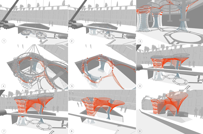
Figura 18.Implantação Local do Processo Utilizando a Técnica de Construção de Malhas.
Referências
ALFARIS, A.; MERELLO, R. The generative multi performance design system. ACADIA, p. 449-455, 2008.
BAURMANN, G. Crocheting algorithms. 2010. Disponível em: <http://aap.cornell.edu/events/upload/baurmann_abstract.pdf>. Acesso em: 26 jan. 2011.
CHISOM, M. The Jacquard loom: its history, development & relationship to computers. 2011. Disponível em: <http://gernot.xarch.at/weave/article_about_jacquard.html>. Acesso em: 24 fev. 2011.
FREY; REAS. Processing software. [n.d.] Disponível em: <http://www.processing.org>[Accessed 10 February 2010].
MALÉ-ALEMANY, M. Machinic control: studio brief 2009-10. Design research lab, volume 13 (Proto Design). England: Architectural Association, 2009.
MANINI, B., ‘Knitting Machine for Producing Tights’, United States Patent, Number 5,226,297, 1993.
RUTTEN, D. Evolutionary principles applied to problem solving. 2010. Disponível em: <http://www.grasshopper3d.com/profiles/blogs/evolutionary-principles>. Acesso em: 21 set. 2010.
SEMPER, G. The four elements of architecture and other writings. England: Cambridge University Press, 1989.
SCHMIDT, K. Toxi libraries for processing. [n.d.] Disponível em: <http://www.grasshopper3d.com/profiles/blogs/evolutionary-principles>. Acesso em: 6 out. 2010.
Schmidt, K., n.d. Toxi libraries for processing. Available at: <http://www.toxiclibs.org>[Accessed 6 October 2010].
Knitectonics
Sanhita Chaturvedi is Architect and Master in New Methods of Digital Fabrication, Design and Urbanism. Actually working at Foster + Partners Architecture.
Esteban Colmenares is Architect and Master in New Methods of Digital Fabrication, Design and Urbanism. Visiting Lecturer at University of Central Lancashire, John McAslan + Partners.
Thiago S. Mundim is Architect and Master in New Methods of Digital Fabrication, Design and Urbanism. Visiting teacher at the Institute for Advance Architecture of Catalonia (IaaC) and actually director at YNOYarchitecture.
How to quote this text: Chaturvedi, S. Colmenares, E. and Mundim, T. S., 2011. Knitectonics, V!RUS, [online] n. 6. [online] Available at: <http://www.nomads.usp.br/virus/virus06/?sec=4&item=2&lang=en>. [Accessed: 05 July 2025].
Abstract
“...techniques that operate on a material level, if we need ideas, will follow from techniques and techniques follow from matter...” - Gottfried Semper (1989).
Can a simple household craft facilitate a proto-tectonic system?
The project Knitectonics aims at exploring digital fabrication systems that facilitate optimized, adaptive and specific integrated architectural solutions (Malé-Alemany, 2009). It is inspired by the beauty of nature systems with their inherent efficiency and performance. The research explored on-site fabrication of monocoques[1] shells, integrating skin and structure along with services and infrastructure, using a simple household technique. It thus embodies a self organized micro system of textures and a macro system of structures. This paper elaborates how the numeric aspects of a textile technique were used, first to digitally imitate the process of assembly and further exploited to develop and visualize a novel fabrication system, based on material research and technical experimentation.
Keywords: Digital fabrication, emergent architecture, evolutionary architecture, textile architecture, knitting, design research.
1. Introduction
A natural harmony has always existed between machines and mathematics, and this synchronization directed scientists to modern day computation. The Jacquard loom, with its wooden punched cards, was the first mechanical device driven by a binary pattern. It brought forth the idea of programming and further inspired Charles Babbage to develop the analytical engine (Chisom, 2011). Ever since the industrial revolution, techniques for manipulation of fibers into textiles have not been domestic craft- based procedures and neither have the materials been mute. Together they have been revolutionary, so much so that today they are used for various high performance purposes like aircraft building. All these techniques are about material placement, to differentiate surface pattern and form geometries. They are in close congruence to architecture but in absence of a design and visualization tool, their potential has not been fully harnessed.
The deep rooted relevance of textiles in architecture is apparent in the theoretical works of the 19th century German architect Gottfried Semper, who deduced textiles to be the first technical art (Semper, 1989). Lars Spuybroek further envisioned soft elements becoming rigid through collaboration using various textile techniques. These theoretical intuitions along with the capacity of available ‘techno textiles’ could be united with simple machinic processes used in the textile industry. To that end, numerous techniques of Interweaving (like fiber placement, 3D weaving and stitching), Intertwining (like braiding and knotting) and Interloping (knitting) were studied and experimented with.
The primary objective of the project was to achieve complex geometries with inherent ‘economy of means’, such that material is placed optimally where it is required. Monocoques, where skin is the structure, visibly illustrate this and the aim was to extend this economy to other parameters of material, machine, infrastructure, energy, time by creating ‘self structuring forms’. The technique of knitting uses the potential of the continuous mono-materials of the fibre realm and presents the possibility to materialize unified structures without formwork, as against other textile techniques which require extensive machine setup and formwork. Hence, re-interpretation of an existing method and articulation of sophisticated programmability of the machinic system to explore novel architectural design processes will be demonstrated here with the technique of knitting.
Figure 1. Household Circular Knitting Machine.
2. Evolution of the Machine
The process followed through the project was a parallel dialogue between analogue experiments, done on a household circular knitting machine (Figure 1) and digital simulation, done in Java language on the ‘Processing’ platform. After understanding the machine, method and metaphor of knitting, the challenge was to explore the tectonic possibilities presented by the technique, resolve the issue of scale as an architectural prototype and adapt the system for on-site deployment. The first step to a solution was to connect two or more machines with a bridge, inspired by Benito Manini’s ‘knitting machine for producing tights’[2]. So though the conceptual prototype design of the machine started with a household circular machine, it evolved through rectilinear, cross and hexagonal configurations, to eventually come back to a circular configuration, connected with bridges in a hexagonal grid (Figure 2).
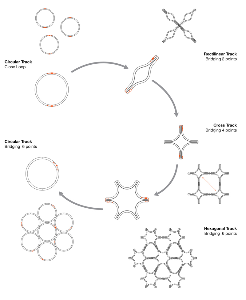
Figure 2. Evolution of the Machine.
Figure 3.Knitting – Attachment – Solidification Rings.
To be realistic as a fabrication process, the digital setup of these circular knitting machines with bridges would require additional processes. To deploy structures without formwork with this system, the proposed ‘knitting ring’ would move up as it knits and the knitted fabric would be tensed using a replica of the machine configuration ‘attachment ring’ on the ground. Another critical aspect was to achieve structural rigidity, the suggested solution for which was to use fibers impregnated with resin, solidified to shape with UV light from the ‘solidification ring’ (Figure 3). To investigate and simulate systemic aspects and topological complexity with the knitting-solidification machine, it became imperative to construct a digital machine. The idea was to create a simulation system that could digitally imitate all parts of the machine and their actions, which together would create a knitted structure. Thus the tools together represent a new language of assembly and will be explained here as three phases.
The first phase of developing a ‘decoding tool’ involved understanding and decoding the knitting action of the machine and the material properties of the fibers used, and then translating them into fabric and its behavior. The tool facilitated in appreciating and speculating patterning, topologies and behavior, beyond the capacity of the analogue machine.
In the second phase simulation helped conceptualize the ‘design apparatus’, with the interface as a fabrication blueprint. Design apparatus is based on the systemic comprehension of a simple machine, wherein the constructed fiber articulates surface and layering seamlessly and the trajectory of a single line gives one, two and three dimensional geometry (Baurmann, 2010). The interface allows selection of size and configuration of machines, type and properties of fibers, dynamics and equilibrium of the system and the course of action of the fiber feeding ‘agent’. The algorithmic routines facilitated the option of pre-programming or real-time sequencing of heads and visualizing the outcome. The digital machinic system was then applied in a selected scenario, to test and demonstrate the tectonic capacity of the method developed.
The third phase proposed a ‘generative tool’ which could be developed to precision in the future, to evaluate, select and optimize. The digital systems offers various ways to set up, sequence and control the machine, such that the system does not provide a single accurate result, but multiple appropriate solutions. The constants of the system, i.e. the ‘chromosomes’ are varied to achieve a random population. These iterations are evaluated against the prescribed parameters and then bred over ten generations to obtain appropriate architectural solutions.
3. Decoding Tool
In the initial phase of digital simulation, the decoding system could simulate different yarn with varying properties, openings, different patterns and solidification, under the effect of gravity and time (Figure 4). The simulation was primarily focused on digitally imitating fabric behavior and patterning, with the understanding of the analogue machine.
The parts of the machine executing different functions were split into tasks in the simulation system, such as the tracks, the yarn feeder and the bridge connections. The simulation was scripted in ‘Processing’ (Frey and Reas, 2010) and for simulating physics an additional library ‘Toxiclibs’ (Schmidt, 2010) was used.
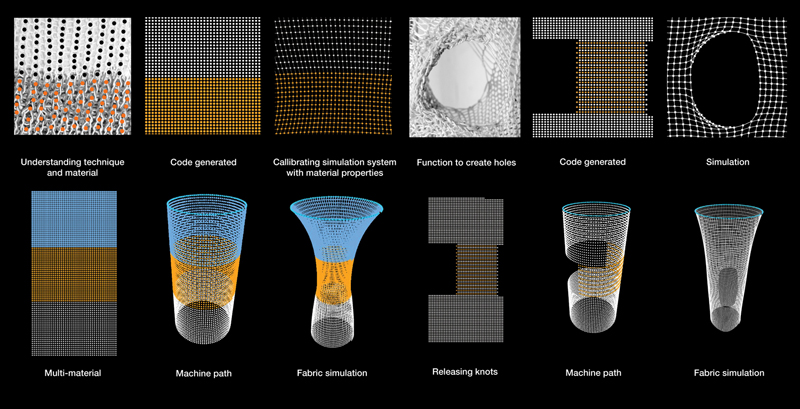
Figure 4.Analogue and Digital Decoding Process.
3. 1. Parts of the System
- Needle: is the smallest performing component of the mechanic system. It inter- loops the yarn to create the knitted fabric, while holding the knot for inter looping the next set of knots.
- Bed of Needles: is a segment of the track, which is a support base for the needles. Each bed has a certain number of needles and a “bridge” at the beginning of it.
- The Bridge: is a point where two beds of a track are linked. These also become the connection points for bridging with other tracks.
- The Track: is composed of six needle beds and it carries the information required to create a specific size machine, i.e. the radius, total number of needles etc. These parameters then determine the specifics of the bed and the needles. Each track has six beds and thus six bridges, every 60 degrees, which connect to other tracks (Figure 5).
Figure 5.Machine Anatomy.
3.2. Knitting Action
The knitting process on a physical knitting machine involves each needle to create a loop. This loop is retained until the yarn interloops to create a new loop, following which it is dropped to create the fabric. So each knot is singularly active on the needle and once it is off the needle as a part of the fabric, it is under collective action. In the simulation, each knot on the needle is represented by a ‘particle’. These ‘particles’ are then dropped just like the knots and the resultant fabric can be described as a ‘number of particles’ connected with ‘springs’, which are the digital equivalent of the yarn.
[1] The term ‘Monocoque’ comes from the greek root ‘mono’ meaning single and the French word ‘coque’ meaning shell and is a construction technique that utilises the external skin to support the structural load.
[2] Benito Manini, 1993. Knitting machine for producing tights. United States Patent, number 5,226,297. 13 July.
3.3. Knitted Fabric
Each yarn used in knitting has specific properties and it was imperative to embed this data into the simulation to get a real picture of the material behavior. As the knitted fabric falls with gravity, the behavior of the yarns governs the behavior of the fabric. So in the simulation script each yarn was imparted the following characteristics.
- Physics: The knots of the fabric are represented by ‘particles’ connected with ‘springs’ from the physics library. These ‘particles’ are subjected to forces of gravity and other springs around them, as the knots are relational and impact each other.
- Yarn Strength: The yarns are differentiated by the strength of the ‘spring’ of each yarn. Spring strength is defined in a range of maximum stretch and maximum compress and has an ideal rest position, such that the springs under all forces are always attempting to come to that rest position.
- Yarn Weight: As the force applied on an object in the product of its mass and the gravitational acceleration to calculate the force on the yarn, gravity is declared as a global variable and weight of each yarn is established in yarn properties (Figure 6).
Figure 6.Material Versioning.
3.4. Machine Dynamics
In conventional knitting, the machine is stationary and the fabric is pressed under rollers and pulled down. In the conceptual machine, the machine moves up while knitting, gravity and ground are utilized to attach and tense the fabric. The following functions are used for simulating real time dynamics of the system.
- Fabric Attachment: This function allows attachment of the fabric to the ground or any other horizontal plane and the distance after which it attaches can be set on the interface. Here the first row of ‘particles’ on the needles of the machine are connected to corresponding points on the attachment plane.
- Machine Movement: This operation enables the machine to move vertically. The movement speed can be adjusted as per the tension required; a tight knit fabric would require a high speed and a loose knit fabric requires a slow speed.
- Tension: This is an absolute necessity for analogue knitting and is done using weights. In the digital system, the tension derived is a combination of machine movement speed and the friction caused by the attachment plane (Figure 7).
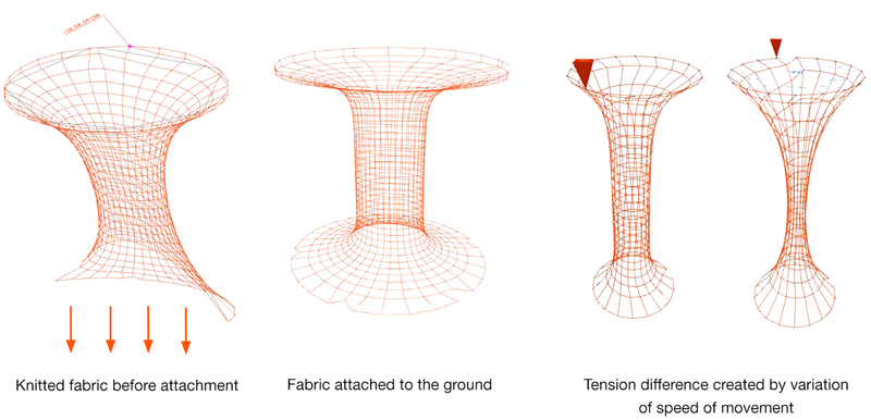
Figure 7.Machine Dynamics.
3.5. Materiality
The implications of knitting multiple yarns simultaneously were studied in analogue experiments. Being in the realm of fiber composites, matrix material for solidifying the yarns was used and eventually, the possibility of the fiber and matrix combination in a single material, i.e. the impregnated yarn, was explored. These were integrated into the simulation.
- Multiple Yarns: Each single yarn has selected properties, thus for combining multiple materials, the simulation creates a new material with a distinctive identity and combines the properties of the different yarns used.
- Solidification: This function imitates the machine and instigates the process of solidification of the yarn after it has been knit. For solidifying a knot, the simulation freezes the springs of the ‘particles’ involved.
- Impregnated Yarn: The knitted fabric can be soft and rigid, hence the digital system also needed the flexibility to selectively solidify a specific yarn and not all yarns. This way the simulation takes into account the structural impregnated yarns (Figure 8).
Figure 8.Materiality – Knitted (magenta) and Solidification (blue).
4. Design Tool
After decoding the knitting action and all the parts of the proposed machine, the tool was used to design. Multiple heads were choreographed to knit along tracks and respond to bridges (Figure 9).

Figure 9.Digital Interface of Design Apparatus.
The yarn head carries the yarn and drops particles connected with springs along the track. Upon introducing the bridge function, the yarn head can move from one track to another. The bridge activation and routine can be predefined on the script or can be modified in real time on the interface. Routines of bridge activation – deactivation and bridge cross-bridge, facilitate in creating connections, bifurcations and topologies.
4. 1. Head Sequences
Further improvements in the machine design led to the deduction that the bridge was not required as a physical element, but rather as an action of the yarn head. At any connection point of two tracks in the hexagonal circle packing grid, the yarn head could perform any of the four prescribed actions. These actions are referred to as ‘sequences’.
- Sequence 0: The ‘sequence 0’ is a command for the yarn head to bypass a connection point.
- Sequence 1: The ‘sequence 1’ for the yarn head to return back.
- Sequence 2: The ‘sequence 2’ for the yarn head to bridge.
- Sequence 3: The ‘sequence 3’ for the yarn head to cross-bridge (Figure 10).
It is important to note here that the ‘connection point’ connects two needles on one track, to two corresponding needles on the other track. So in sequence 2, the yarn head bridges two needles located in parallel, whereas in sequence 3, the yarn head bridges across two needles located in diagonal and stitches tubes together. Each yarn head can therefore be prescribed a routine of ‘n’ number of sequences and this routine can repeat endlessly.
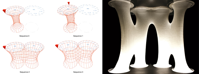
Figure 10.Digital Sequences and an Analogue Instance of Sequence Combination.
4.2. Yarn Head Initiation Point
In a closed hexagonal grid configuration of three or more tracks, there is an external perimeter and an internal perimeter, enclosed within the tracks. The initiation point of the yarn head on the external versus the internal perimeter, can yield diverse results. The starting point of a yarn head can be directed, by giving it a track, needle bed and needle number location and also the direction of movement as clockwise or anticlockwise. As the yarn head path is prescribed by the routine of sequences, the knitted outcome is specific to the initiation point in the configuration of tracks.
4.3. Dropping Knots
The knit density can be changed and holes can be created by dropping knots from the needles. The idea of the digital machine is to experiment with topology and openings at an appreciable scale, so the focus was on dropping knots not for single needles, but for a group of needles. The simulation system offers the possibility of dropping a whole track or a certain needle bed of the track, or just the bridge as per the design prerequisite on the ‘track functions’ tab of the design interface (Figure 11).
4.4. Yarn Head Path and Number
As mentioned earlier, there is an external and internal perimeter enclosed within the tracks. These perimeters - the track itself (large perimeter) and the interstices created (small perimeter) - can both be employed as paths for the yarn heads. Interestingly, the speed of machine movement becomes critical here as time required for a cycle on each perimeter is significantly different, either causing the knit on the inside to be very loose or on the outside to be very tense. This can be countered by increasing the number of heads on the larger perimeter. The interstices give the opportunity to vary the enclosed knitted volumes and create structural elements, sub divisions or shafts (Figure 11).
Figure 11.Dropping Knots Interface / Model with Variable Perimeters.
4.5. Attachment Control
Along with all the above functions in the digital system, the option to attach or not attach at any specific moment and the possibility to attach to the ground or another horizontal plane, opens up a new domain of topologies and morphologies (Figure 12).
Figure 12.Seven Track Configuration and Possible Outcome.
5. Architectural Application
The design interface was developed from the understanding of analogue techniques, machinic systems and material behavior. The design tool contains all the knowledge gained from the decoding tool and imparts the opportunity to envision knitting as a principle of construction. The choreography of the heads determines the way the material is deposited and defines a new vocabulary for architecture.
The setup enables one to achieve complex topological surfaces as the machine has a one to one relationship to the material result and the natural local coordinates create a global- local structure. Additionally, to address macro level and micro level issues with the system, the idea of a machine of variable sizes within the hexagonal grid was introduced, hence imparting it the capacity to integrate multiple scales, resolutions and functions. The tectonic aspects are addressed at two levels by the system, firstly at the spatial or programmatic level, providing space, structure and punctures, and secondly at the performative level, providing micro infrastructure, embedded services and performative skin (Figures 13a, 13b and 13c).
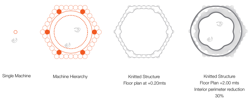
Figure 13a.Size and Hierarchy of Machines.
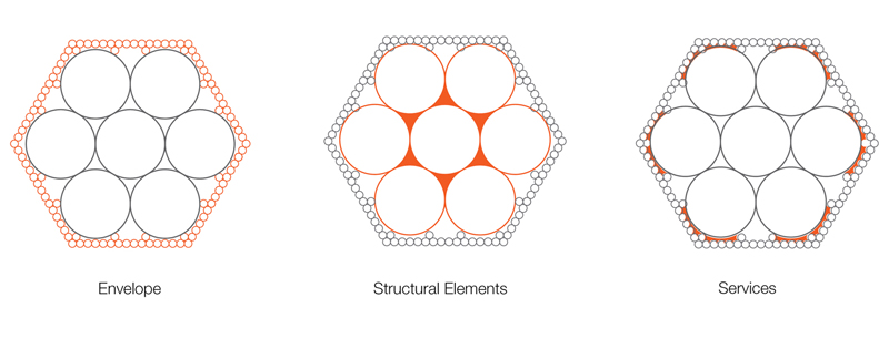
Figure 13b.Resolution and Relationship to Tectonic Elements.
Figure 13c.Analogue – Digital Relationship of Tectonic Elements.
The system was analyzed to appropriately locate the application of the reinterpreted method. Being multi-scalar, modular and collaborative, it has the potential to attend to various scales, programmes and sites and can adapt to site constraints with the flexible deployment and material usage approaches available. The nature of the system establishes its prototypical application in the realm of quick deployment, minimal impact and integrated mono-system. The multiple interconnected layers give the opportunity to embed micro infrastructure and services into a unified structure, making it suitable for macro level infrastructure.
For testing the system, the infrastructure development for a new transport technology - Personal Rapid Transit (PRT) system in the city of Bath - was chosen as the application scenario. The aesthetics, lightness and transparency of knitted fabric, aptly situate it in the deep rooted culture of textiles in England’s historic towns. The PRT system demonstrates resonance to knitted topologies with the proposed machinic system for its concepts of continuity/ bifurcations, networks/ nodes. (Figures 14a and 14b)
Figure 14a.Architectural Application / PRT Station Canopy in Bath.
Figure 14b.Roof Plan of PRT Station Canopy, Demonstrating the Design Tool.
Different sites where the PRT infrastructure extends into other civic infrastructure were selected in order to explore the prototypical nature of the system on the basis of programme, scale, context, machine configurations and material (Figure 15). Though all sites use the same system, the design and deployment approach to each varied, thus testing and demonstrating the feasibility of the system and also defining its limits and ranges.
Figure 15.Application / Art Museum and Underground PRT Station in Bath.
6. Generative Tool
The design tool thus facilitates in realizing most of the tasks dealt with in conventional materials and machines in architecture. The digital machinic system offers several set up options, in terms of the number of tracks, their configuration, bridge connections, number of yarn heads, their start point and the yarn type used. Along with the attachment, movement and solidification control and most importantly the sequences prescribed to the yarn heads, the permutations and combinations possible are endless.
The system provides multiple solutions with equal suitability, thus making it extremely complex to solve in a linear manner (Alfaris and Merello, 2008). In order to locate appropriate architectural solutions, only a generative system would be capable of evaluating, selecting and optimizing architectural requisites.
The third tool - generative algorithm - was a modest attempt to generate populations of valuable architectural solutions from the proposed machinic system on the basis of structure and space. With enhanced sophistication and precision, the procedure could be an objective optimization tool and in the future could be extended to other physical and performative parameters like openings, heights, surface resolution, layering etc.
To understand generative systems, Anad Alfaris and Riccardo Merello’s paper ‘The Generative Multi Performance Design System’, presented at the ACADIA 2008 was referenced. The paper proposes a framework to generate solutions within design space defined by the system’s design language, with the integration of various performance criteria. The system is composed of four phases, namely, synthesis, analysis, evaluation and optimization. Within these cycles, modules store parameters, constants and constraints. To test the feasibility of a generative system by comparing different iterations to find the most optimum, these cycles were applied to the digital machinic system.
- Synthesis: The basic architectural parameters of structure and space were established as the design intentions.
- Analysis: Since the forces of gravity and pull on the knitting machine control the fabric, the structure is characterized by the tension in the knots. The space is embodied in the dimension of the enclosure created.
- Evaluation: To understand the stretch in different regions and the cross- sectional changes in the knitted fabric along both axes, analogue models were studied.
Computationally, for structural evaluation, the system measures the tensile forces (spring strength in comparison to the rest position strength) acting on each knot and categorizes them to be: over stretched, under stretched and ideally stretched, on the basis of analogue calibration models. In proposed simulation, ideal stretch is typified with green color, maximum under stretch with blue color and the moderate stretch situation with yellow. The red color depicts maximum over stretch possible, beyond which the spring is at breaking point and hence unsuitable, shown in black.
From analogue models it was also concluded that a knitted fabric typically stretches up to a third of original length. Considering the self organizing behavior of knots, the implication of the increase in length is visible in the reduced cross section of the tube. Thus for spatial evaluation the minimum dimensions for a habitable space were established based on the machine size and the percentage decrease in cross section after stretching, and the options were evaluated against that minimum dimension, discarding infeasible options (Figure 16).
- Optimization: Typically the most optimum solution could be chosen by comparing it against the ‘predefined best solution’. But the proposed system has no preconceived ideal solutions, thus creating the challenge to locate the most optimum solutions through a series of generations.
‘Evolution starts from a population of randomly generated design solutions to guide the evolution. The purpose is not to produce a global optimum solution, but rather to direct the evolutionary process to produce populations of good solutions’ (Alfaris and Merello, 2008). This evolutionary algorithm can be decomposed into five stages: fitness function, selection mechanism, coupling, and mating and mutation introduction (Rutten, 2010). Applying these principles to develop an optimization tool, the constants or the chromosomes were set with respect to track configurations and yarn head locations. The first population of one hundred iterations was then generated by random combinations of sequences 0, 1, 2 and 3 (0 = continue, 1 = go back, 2 = bridge and 3 = cross-bridge) which are comparable to the genes or the DNA in biological evolution.
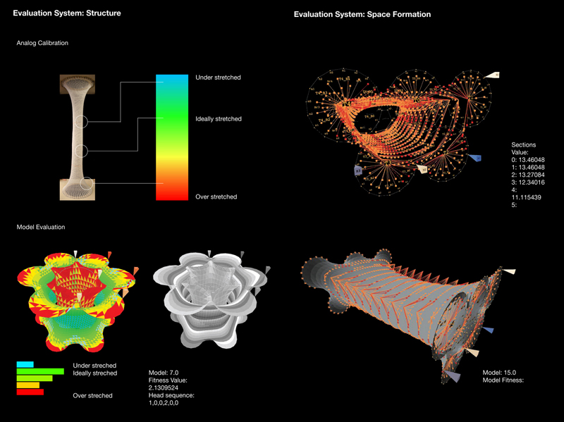
Figure 16.Evaluation Parameters of Structure and Space.
The iterations were evaluated against the parameters of structure and space and assigned a fitness value. For structural evaluation, fitness is determined by the number of ideally stretched knots, with a positive weight value and the number of under and over stretched knots, with a negative weight value. These were then averaged to get a fitness value. Similarly, for spatial evaluation, the distance of ‘space cells’ on each segment of the surface from the central axis is measured against the ideal prescribed distance and then averaged across the entire envelope.
Of the hundred iterations, ten iterations with the highest combined structural and spatial fitness value are selected as the best. Each of these then mates with the other ten iterations, to generate the offspring of the second generation. This process is repeated for ten generations. Interestingly, the resulting ten iterations tend to become self similar by the seventh generation (Figure 17).
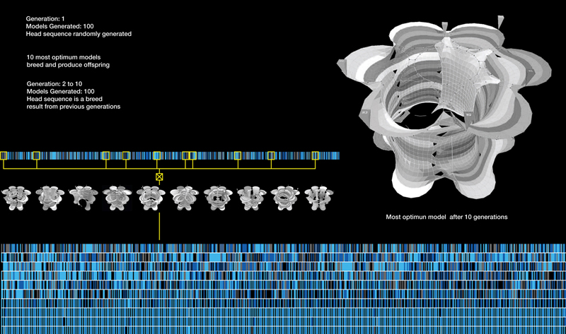
Figure 17.Genetic Algorithm Developing Iterations over Ten Generations.
7. Conclusion
A constructed fibre articulates surface and layering, as trajectory of a single line gives one/ two/ three dimensional geometry - Self- similar and repetitive, loops bind and string seamlessly - Local rules define a language of assembly that yields dynamic global results - A mute material becomes mutational. Such is the richness of a simple household craft.
The pre-designed technique through pre- programmed instructions on the jacquard loom, gave way to computation. With an on-site fabrication machine, inspired by a household technique, which gets feedback from materiality and responds to it, the three tools of the proposed system use computation to design, visualize, instruct and fabricate in real-time.
‘Knitectonics’ is our humble effort at the re-interpretation of an existing technique and machinic system to articulate novel architectural design processes. Our attempt, in a limited capacity, has been to explore diverse issues of machinic systems, materiality, deployment, topology, layering, scale, parametrics, algorithms etc.
Contemplating a future for the project, there are various potential concerns to focus on. As mentioned earlier, genetic algorithm is a possibility as an objective optimization tool, but in isolation of a number of subjective concerns. We recognize that the evaluation parameters of the algorithm require enhanced sophistication and precision and also technical inputs from specialists. Another pragmatic approach could be to build a working prototype of the machine in order to appreciate the structural potential of the technique and get feedback from materiality. This could potentially present a pristine stratum to exploit fibre composites in architecture.
The vast world of textiles – techniques, materials, processes, machines etc - is a rather intimidating world. For the sake of simplicity, we had defined a small and precise set of working tools with respect to the technique of knitting. The stitch we considered here was interlooping, on a circular weft knitting machine. The surface consistency can be interrupted by utilizing different stitch types and topologies variations can be created by increasing or decreasing the knot size (tuck stitch and rib stitch). Applying principles of warp knitting machines could escort us to the realm of high strength 3d spacer fabrics. We could thus expand the technical tool set and study the systemic implications.
Turing proposed the concept of ‘computation’ based on binary notations and intended the ‘universal machine’ to represent function of any existing machine and thus the question of extending the idea of notation into our computational system and directly using the machine. We see opportunity in the idea of the notation in translating our digital commands to a physical machine, similar to the code used by the contemporary flat bed knitting machines. Our preliminary effort at using algorithmic routines was in sequencing the movement of the yarn head on the needle bed, but can be continued to individual needles; and further widened to stitch matrix taxonomy that organizes stitches according to spatial qualities like enclosure, transparency and interdependence etc.
Since our machinic system is a tension based system and knitting has a self- organizing behaviour, all the resultant surfaces created are minimal surfaces. The issue of surface and geometry could be explored beyond the family of minimal surfaces, possibly by subjecting the knitted fabric to additional loads, pressures, strains, deformations. For instance, the knitted structure could be treated locally and non- uniformly during the streamline machine process, by using the possibility of differential attachment or solidification. The machine and the material output have had a direct relationship for us, but we appreciate the potential of ‘controlling material’ as opposed to ‘self- organization’ alone.
Another idea is to investigate the application of our machine as a system to fabricate individual architectural components that can then be organized together to form a whole and not the structure in totality.
It is interesting to note that the aesthetics were derived from the functional aspects of the design, which in turn were deduced from the technical logic of construction system. Thus the ‘process of making’ was as ‘the DNA of the creation’, where quantitative pursuits become qualitative.
These are the first steps in the research and development of a knitting-based digital parametric system that enables real-time fabrication to intelligently interact with the parameters, propose an ‘optimized solution’ bracket within which a designer could create and communicate a design to the deployment machines (Figure 18). But most importantly, this parametric process of decoding, designing and generating, could be utilized with any other machinic process to develop novel fabrication methods for architecture.
Figure 18.On-site Deployment Process Using Knitting Technique.
References
Alfaris, A. and Merello, R., 2008. The generative multi performance design system. ACADIA, pp. 449-455.
Baurmann, G., 2010. Crocheting algorithms. Available at: <http://aap.cornell.edu/events/upload/baurmann_abstract.pdf>[Accessed 26 January 2011].
Chisom, M., 2011. The Jacquard loom: its history, development & relationship to computers. Available at: <http://gernot.xarch.at/weave/article_about_jacquard.html>[Accessed 24 February 2011].
Frey and Reas, n.d. Processing software. Available at: <http://www.processing.org>[Accessed 10 February 2010].
Malé-Alemany, M., 2009. Machinic control: studio brief 2009-10. Design research lab, volume 13 (Proto Design). England: Architectural Association.
Manini, B. 1993. ‘Knitting Machine for Producing Tights’, United States Patent, Number 5,226,297.
Rutten, D., 2010. Evolutionary principles applied to problem solving. Available at: <http://www.grasshopper3d.com/profiles/blogs/evolutionary-principles>[Accessed 21 September 2010].
Semper, G., 1989. The four elements of architecture and other writings. England: Cambridge University Press.
Rutten, D., 2010. Evolutionary principles applied to problem solving. Available at: <http://www.grasshopper3d.com/profiles/blogs/evolutionary-principles>[Accessed 21 September 2010].
Schmidt, K., n.d. Toxi libraries for processing. Available at: <http://www.toxiclibs.org>[Accessed 6 October 2010].